JPL's Wireless Communication Reference WebsiteChapter: Wireless Channels.
|
| Topographical terrain data is used extensively to predict
propagation conditions, to optimally select locations for installing cellular base stations.
In an interview, Daniel Davarsilvatham of Bellcore discusses how adequate planning can avoid or reduce costly field tests. |
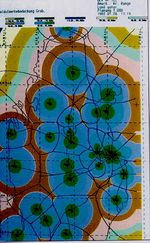
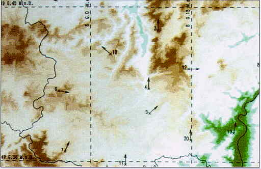 Source: Siemens TORNADO D Cellular Planning Tool |
| In a rough coverage estimation, pathloss is computed using a basic propagation model, such as Egli's model, considering neither the topography nor terrain features in great detail. If no interference were present and if omni-directional antennas were used, such coverage plots tend to show circular cell layouts. However, real-life cell layouts substantially differ from the theoretical hexagonal or circular lay-out. |
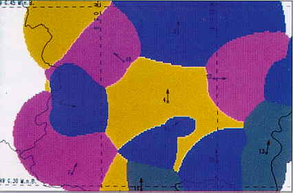 Source: Siemens TORNADO D Cellular Planning Tool |
| In practical cell panning, pathloss is computed from the terrain features and antenna data. Received signal powers and interference power levels, determine to coverage of each base station. Mathematical methods have been developed to calculate the signal outage probability, given all these propagation parameters. The link budget is more of a back-of-the-envelope alternative. |
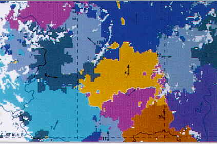 Source: Siemens TORNADO D Cellular Planning Tool |
In the above path profile, the most appropriate path loss model depends on the receive location:
|
Figure: Average path loss versus distance in UHF bands, measured in Northern Germany. (a, green): forestrial terrain (b, orange): open area (grey): Average of (a) and (b) (black): Egli's model
| ||
|
Models such as the Egli Path Loss Law
can be used for a rough coverage estimation.
However, the prediction error standard deviation is on the order of 12 dB.
Compare the predicted smooth cell boundaries by the more accurate estimates in the screen displays above.
On the right: Results generated by the TORNADO D planning tool by Siemens AG for cellular telephone at 900 MHz. (Qatar, Arabian Peninsula ) |
 Source: Siemens TORNADO D Cellular Planning Tool |
 |
 |
|
 |
||
 |
SPECSee the Special Purpose Embedded Path Loss Predictor, a spread sheet to forecast path loss.
| Effect of antenna height | Effect of frequency | Effect of distance | ||
| Free space | none | 20 log f | 20 log d | |
| Theoretical plane earth | 6 dB/oct | none | 40 log d | |
| Egli plane earth | 6 db/oct | 20 log f | 40 log d | |
| Measured urban | 6 dB/oct | 20 log f | 32 log d |


![]()