JPL's Wireless Communication Reference WebsiteChapter: Wireless Channels |
For propagation distances d much larger than the antenna size, the far field of the electromagnetic wave dominates all other components. That is, we are allowed to model the radiating antenna as a point source with negligible physical dimensions. In such case, the energy radiated by an omni-directional antenna is spread over the surface of a sphere. This allows us to analyse the effect of distance on the received signal power.
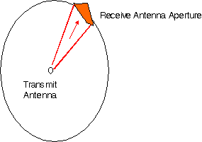
| Figure: Transmit antenna modelled as a point source. Transmit power is spread over the surface area of a hypothetical sphere. The receiver antenna has an aperture A, illustrated in orange. |
The surface area of a sphere of radius d is 4pd2. The power density w at distance d from a transmitter with power pT and antenna gain Gt is
w = pT Gt/ (4 p d2).
The available power pR at a receive antenna with gain GR is
![]()
where A is the effective area or `aperture' of the antenna, with GR = 4p A / l2. The wavelength l is c / fc with c the velocity of light and fc the carrier frequency. The product Gt pT is called the effectively radiated power (ERP) of the transmitter.
![]()
Engineers speak about a "20 log d" path loss law.
 Free Space Loss Calculator
![]() .
.
![]()


![]()