 |
JPL's Wireless Communication Reference WebsiteChapter: Wireless Propagation Channels
|

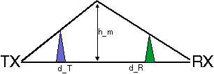
Figure: Path profile model for (single) knife edge diffraction
If the direct line-of-sight is obstructed by a single knife-edge type of obstacle, with height hm we define the following diffraction parameter v:
![]()
where dt and dR are the terminal distances from the knife edge. The diffraction loss, additional to free space loss and expressed in dB, can be closely approximated by
| AD=0 | if v < 0 | |
| AD=6 + 9 v + 1.27 v2 | if 0 < v < 2.4 | |
| AD=13 + 20 log v | if v >2.4 |
 Single Knife Edge Calculator
Approximate techniques to compute the diffraction loss over multiple knife edges have been proposed by

The method by Bullington defines a new `effective' obstacle at the point where the line-of-sight from the two antennas cross.

Epstein and Peterson suggested to draw lines-of-sight between relevant obstacles, and to add the diffraction losses at each obstacle.

Deygout suggested to search the `main' obstacle, i.e., the point with the highest value of v along the path. Diffraction losses over `secondary' obstacles are added to the diffraction loss over the main obstacle.
Many measurements of propagation losses for paths with combined diffraction and ground reflection losses indicate that knife edge type of obstacles significantly reduce ground wave losses. Blomquist suggested two methods to find the total loss:
![]()
and the empirical formula
![]()
where Afs the free space loss, AR the ground reflection loss and AD the multiple knife-edge diffraction loss in dB values.