JPL's Wireless Communication Reference Website
Chapter: Wireless Channels
|
If we consider the effect of the earth surface, the expressions for the received signal become more complicated than in case of free space propagation. The main effect is that signals reflected off the earth surface may (partially) cancel the line of sight wave.
![]()
with Rc the reflection coefficient and E0 the field strength for propagation in free space. For AM broadcasting propagtion models these full expressions are relavant and have been used to create frequency plans for mediumwave and long wave broadcasting.
For VHF and higher frequency, this expression can be interpreted as the complex sum of a direct line-of-sight wave, a ground-reflected wave and a surface wave. The phasor sum of the first and second term is known as the `space wave'.
For a horizontally-polarized wave incident on the surface of a perfectly smooth earth,

![]() ,
,
where er is the relative dielectric constant of the earth, Y is the angle of incidence (between the radio ray and the earth surface) and x = s/(2 p fc e0) with s the conductivity of the ground and e0 the dielectric constant of vacuum. So, x = s/(we0)=18 109s/f.
For vertical polarization
![]()
| Surface | Conductivity s | Relative Dielectric Constant er | |||||||||||||||||
| | | | | |
|
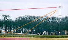
Two-ray model for UHF propagation over a plane reflecting earth.
|
The phase difference between the direct and the ground-reflected wave can be found from the two-ray approximation considering only a line-of-sight and a ground reflection. Denoting the transmit and receive antenna heights as hT and hR, respectively, the phase difference can be expressed as
![]()
![]() Exercise
Exercise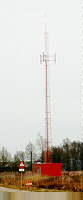 Consider a base station antenna with hT= 30 meters and a mobile antenna with hR= 2 meters.
The mobile is d = 1,000 meters (1 km) separated from
the base station. The carrier frequency is 1 GHz.
Consider a base station antenna with hT= 30 meters and a mobile antenna with hR= 2 meters.
The mobile is d = 1,000 meters (1 km) separated from
the base station. The carrier frequency is 1 GHz.
The exact expression for the phase difference is not very convenient for further analysis. For large propagation ranges, i.e., for large d, one can use an approximation based on
![]()
This results in the approximate, but mostly quite accurate phase difference
![]() ,
,
This, and an approximation for the reflection coefficient give an often used two-ray model for plane earth propagation. For large d, (d >> 5hT hR ), the reflection coefficient tends to -1, so the received signal power becomes
![]()
 Here, the distance
![]()
acts as a turnover point. For this distance, the argument of the sine becomes equal to p/4. For carrier frequencies around 900 MHz or 1 GHz, a base station height of 30 meter and a mobile antenna height of 2 meter, the turnover distance is about 100 meters. Hence for macro-cellular systems, distances beyond the turnover distance are more relevant.
The full path loss expression shows an interference pattern of the line-of-sight and the ground-reflected wave for relatively short ranges, and a rapid decay of the signal power beyond the turnover distance. See also: a plot of loss versus distance for various antenna heights.
For propagation distances substantially beyond the turnover point path loss tends to the fourth power distance law:
![]()
 Answer.
 Experiments
confirm that in macro-cellular links over smooth, plane terrain, the received
signal power (expressed in dB) decreases with "40 log d". Also
a "6 dB/octave" height gain is experienced: doubling the antenna height
increases the received power by a factor 4. These two effects are correctly predicted
by the two-ray model.
Experiments
confirm that in macro-cellular links over smooth, plane terrain, the received
signal power (expressed in dB) decreases with "40 log d". Also
a "6 dB/octave" height gain is experienced: doubling the antenna height
increases the received power by a factor 4. These two effects are correctly predicted
by the two-ray model.
However, in contrast to the theoretical plane earth loss, Egli measured a significant increase of the path loss with the carrier frequency fc for ranges 1< d < 50 km. He proposed the semi-empirical model
![]()
i.e., he introduced a frequency dependent empirical correction (40 MHz/fc)2 for carrier frequencies 30 MHz < fc < 1 GHz.
For communication at short range, this formula looses its accuracy because the reflection coefficient is not necessarily close to -1. For d << hT hR / 4l, free space propagation is more appropriate, but a number of significant reflections against the earth surface must be anticipated. However, these are often hard to distinguish from reflections against obstacles in the vicinity of the antenna site. Moreover, in streets with high buildings, guided propagation may occur.
Egli Path Loss CalculatorDisclaimer: Executable software programs are provided with no guarantee whatsoever.


 .
.
![]()