 |
JPL's Wireless Communication Reference WebsiteChapter: Analog and Digital Transmission Section: Spread Spectrum , Hybrid DS/FH WISSCE system, BER estimates |
Contributed by Jack Glas, Lucent.
This page covers the performance of an hybrid frequency hopping / direct sequence spread spectrum radio network, in particular the according to the WISSCE system concept. The results of this page are used to calculate the local-mean and instantaneous BER
A number of system properties cause a reduction of the SNR level at the input of the analog to digital conversion. Both non-ideal despreading and multi-access interference degrade the pre-detection SNR value.
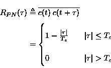
In reality the despreading operation will not be perfect for two reasons: there will always be a misalignment in time between the received signal and the local DS spreading code-generator, secondly there is also an input filter present which affects the received signal.
 |
where ![]() is the misalignment (timing-error) and Tc is equal
to a chip-period. A power correction factor to account for this
timing-error is:
is the misalignment (timing-error) and Tc is equal
to a chip-period. A power correction factor to account for this
timing-error is:
| |
During acquisition this loss may reach 3 dB.
 |
where S(f) is the power spectral density of the input-signal and
![]() the transfer function of the input filter. A
practical situation is illustrated in figure 1, where
a second order butterworth filter is used with a bandwidth equal to
the chip-rate. The power-loss in this example is 0.5 dB.
the transfer function of the input filter. A
practical situation is illustrated in figure 1, where
a second order butterworth filter is used with a bandwidth equal to
the chip-rate. The power-loss in this example is 0.5 dB.
This effect results in a trade-off: a narrow filter smooths the autocorrelation curve, but also reduces the output noise power.
Multi-access is both the essence and the limitation of CDMA systems. The limit on the maximal number of users results from the amount of interference present in the channel and the desired BER.
Multi-access (MA) interference is present when more than one transmitter is active at the same time. A common way to incorporate multi-access interference in the BER analysis is by modelling this interference as a Gaussian noise component [Pur77,WM92,Ger85]. This approach however assumes that there are numerous interferers which are all received with equal power.
As WISSCE applies a non-cellular transmission concept, the received signal from all users cannot be kept constant by means of power control. To create a handle on this problem, two groups of interferers are distinguished:
There is no clear separation between the two categories. A rule of thumb can be that as long as the signal-power from a user after despreading exceeds the signal-power from the intended user, that user belongs to the category of near-users.
This kind of interference is caused by a fairly large group of transmitters relatively far from the reference transmitter. The analysis of this interference is based on concepts from [Ger85,Ger86,Pur77,PS77] adapted for a DS/FH system. If the number of interferers is large, the pseudo-random noise sequences can be assumed to be random. This assumption allows us to derive the variance of the sum of all the far-interference [Roe77]. This variance is equal to the far-interference power and therefore gives the SNR degradation due to far MA-interference. This is illustrated by the following equation for the total detected in energy of a symbol at time n:
![\begin{displaymath}
Z(n) = B_{input} T_s N_0/2 + E_s + S~ T_s \text{Var} \left [\sum _{k
\neq i} I_{k,i}(n) \right ] \;.\end{displaymath}](images/img7_3.gif) |
S is the power of the received desired signal and Ts represents the time duration of a symbol period. The first term (BinputN0/2) at the right hand side represents noise energy that passes the predetection filter during a symbol time. N0 is the single sided noise spectral power density [Pro89, p.156]. The second term is the desired energy term (energy per symbol):
| |
Ik,i(n) denotes the amplitude ratio between multi-access interference (user k) and the user signal (user i) during the nth symbol. The variance of this term is multiplied with the energy per symbol to obtain the interference energy per symbol.
![\begin{displaymath}
I_{k,i}(n) = T_s^{-1} \left [ \delta \left (f\;_i^{n}, f\;_...
...{n},
f\;_k^{n+1} \right ) ~ \widehat{R}_{i,k}(\tau_k) \right ]\end{displaymath}](images/img9_3.gif) |
where the Kronecker function ![]()
![]() is defined by
is defined by
![]() (u,v) = 1, if u = v and
(u,v) = 1, if u = v and ![]() (u,v) = 0 otherwise.
fin is the frequency hopping code for user i during symbol
period n.
(u,v) = 0 otherwise.
fin is the frequency hopping code for user i during symbol
period n. ![]() k is the relative time-delay between the received
signals from the intended user and the interfering user k.
k is the relative time-delay between the received
signals from the intended user and the interfering user k.
![]() and
and ![]() are partial
cross-correlation terms [SP80].
are partial
cross-correlation terms [SP80].
As a result the first term corresponds to a hit of the users k and
i during the earlier part of symbol period n, while the second term
corresponds to a hit during the later part of this symbol period. It
is also leads to the conclusion that the partial cross-correlation
functions ![]() and
and ![]() have only
influence if a hit occurs.
have only
influence if a hit occurs.
It is clear that the MA-interference could be divided into two partial interference terms (as illustrated in figure 2). In this figure ``code 1'' of the reference user and ``code k'' of an interfering user are partially overlapping. One term is responsible for the interference in the first part of symbol period and the other term for the second part.
From the figure it is also clear that in a hybrid DS/FH system, there is at most 1 (partial) hit per symbol-period. This gives:
Taking this into account, formula for the MA-interference can be written as:
| |
in which R'k,i![]() is defined as:
is defined as:
 |
ck expresses the kth chip of a pn-code, while ![]() k1 and
k1 and
![]() k2 are related to
k2 are related to ![]() k in the following way:
k in the following way:

This equation for
R'k,i![]() is illustrated in
figure 3. In this figure the sequences i and k
overlap for 5 1/3 chip period.
is illustrated in
figure 3. In this figure the sequences i and k
overlap for 5 1/3 chip period.
An integer l is now defined which is equal to the number of complete
overlapping chips (![]()
![]()
![]() ,
, ![]() ). This number is negative if the later part of
code i overlaps with code k. In the example of figure
3 l is equal to 5. The integral for
R'k,i
). This number is negative if the later part of
code i overlaps with code k. In the example of figure
3 l is equal to 5. The integral for
R'k,i![]() can be written as:
can be written as:
| |
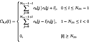
where the first term corresponds to the summation of all ``dark'' overlaps in figure 3 and the second term corresponds to sum of all ``light'' overlaps. Ck, i(l) is the discrete aperiodic cross correlation function [PS77]:
 |
where the usage of square-braces expresses the time-discreteness of the pn-codes. If a hit occurs between the intended and interfering user, the variance of the multi-access interference term in the equation for the MA-interference is:
![\begin{displaymath}
\text{Var}\left [~I_{k,i}\right ] = {\sigma^2_{k,i}} = \fra...
...T_s^3} \int _{-T_s} ^{T_s} R{'}_{k,i}^2 (\tau_k) \; d\tau_k \;.\end{displaymath}](images/img26_3.gif) |
The right hand side can be written as (compare with [Roe77,Ger86]):
![\begin{displaymath}
\frac{1}{2 \;T_s^3} E \left [ \int_ {-T_s} ^{T_s} R{'}_{k,i...
...= \frac{1}{6\, N_{\text{DS}}} \; E \left [
\rho_{k,i} \right ]\end{displaymath}](images/img27_3.gif) |
in which:
 |
At this point we will make use of the common assumption that the applied pseudo noise sequences (pn-codes) are random [Roe77,Ger85,Ger86,Pur77,PS77]. After calculation follows for random sequences:
This yields:
![\begin{displaymath}
E \left [\sigma^2_{k,i} \right ] = \frac{1 }{3 \;N_{\text{DS}}} \;.\end{displaymath}](images/img30_3.gif) |
The power in the multi-access far-interference term:
![\begin{displaymath}
I_{FAR} ~=~ E \left [ \; p_{\text{hit}}(k,K_{FAR}) \right ]...
... \frac{p_{\text{hit}}(k,K_{\text{FAR}})}{ 3\;
N_{\text{DS}} }\end{displaymath}](images/img31_3.gif) |
in which E[phit(k,KFAR)] is the mean number of far-interferers that ``hit'' the reference user in the used frequency-hop channel. Es denotes the energy per symbol: S Ts.
Concerning the MA-interference the conclusion can be drawn that every far-user that hits the reference user during a FH-period contributes maximally 1/3 NDS times the desired signal power. To enable the analysis the power of all interfering users was assumed to be equal to the desired power so the equation for the total MA-interference above provides a number on the interference for a worst case scenario.
Near interference is more problematic in the sense that it can completely block frequency-hopping channels. When too large a number of such near-users are active, communication is not possible. For this reason the number of near-interferers allowed in the system is limited. The hit-probability (Phit) is determinative for the performance.
The number of near-users that can be allowed is also determined by the kind of error-correction that is applied. During system-specification it was required at least two frequency-hopping channels have no near-interference. The system specification shows that NFH is equal to 7 which means that it is likely that there are three near-interference free FH-channels.
In this section we saw that the SNR at the input of the A/D converter (after FH-despreading but before DS-despreading) is degraded by: