 |
JPL's Wireless Communication Reference WebsiteChapter:
Analog and Digital Transmission
|
This page deals with the receiver functions necessary to align the received and locally generated codes and to keep these codes aligned. These functions are acquisition and tracking, respectively.

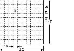
Figure: Phase/frequency uncertainty region.
X denotes the received frequency and phase of the wanted signal.
As the time and frequency resolution is limited during each trial, this rectangle can be subdivided into smaller rectangles with dimension Delta_t and Delta_omega . These smaller rectangles are called cells. By searching these cells the receiver can determine the correct code- phase and frequency. Of course, the dimensions of the cells must be selected in accordance with the code correlation properties, the transmit bandwidth and the observation time in each trial. Various techniques exist for finding the correct code- phase and frequency, i.e., searching the cells in the phase/frequency uncertainty region.
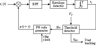
As an example the simple and often used single-dwell serial-search technique will be discussed here. The name of this technique means that integration in the system takes place over a fixed time (single-dwell) and that the phase/frequency uncertainty region is linearly searched (serial-search).

FIgure: Block diagram of the single-dwell serial-search system.
Its operation is rather simple. The output of the local code generator is a time-shifted version p(t + tau) of the code sequence used by the transmitter. The bandpass filter (BPF) is centered at the carrier frequency of the received signal and has a bandwidth equal to the data bandwidth. It filters the product of the received signal and the locally generated code. The output of the integrator is proportional to the autocorrelation function of the code, with offset tau. Then the integrator output is compared against a threshold V_T. If the signal is below the threshold, the phase or the frequency of the locally generated code will be increased to the next cell. If the signal is above the threshold, then the correct code phase and frequency have been found and the receiver will start tracking.

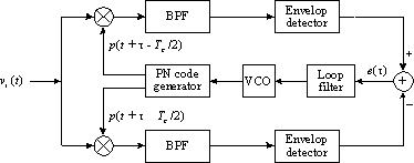
Figure: Block diagram of a DLL.
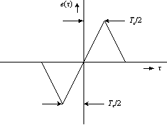
The received signal is divided (by a constant factor of two to remove BPSK modulation) and then multiplied with an early (half-chip early) and a late (half-chip late) version of the locally generated code. Both signals are then bandpass filtered. this gives the "early and late" correlation signals. After filtering, these correlation signals are envelope-detected. Then, the outputs of the envelope detectors are subtracted from each other. This results in an error signal (see Figure) which is proportional to
                     Tc                           Tc
      abs{  Rc(tau + ---) }   -    abs{  Rc(tau - ---) }
                      2                            2
After filtering, this error signal can be used to control a voltage-controlled oscillator which drives the local
code generator. Its output chip rate will increase when the local code lags the received code and decrease when the local code leads the received one.

Figure: Error voltage in DLL, versus time offset tau between receive signal and the locally generated copy.
In a multipath channel, the above "S" curve may be distorted due to time-dispersion in the received signal.