 |
JPL's Wireless Communication Reference WebsiteChapter:
Analog and Digital Transmission
|
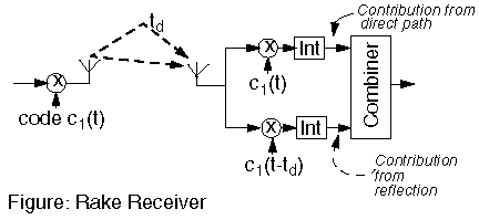
The rake receiver is designed to optimally detected a DS-CDMA signal transmitted over a dispersive multipath channel.
 | Different reflected waves arrive with different delays. A rake receiver can detect these different signals separately. These signals are then combined, using the diversity technique called maximum ratio combining. |
Considering antipodal (i.e., BPSK-type) of DS-CDMA, we denote the transmit waveform as m0 for a digital "0" and -m0 for a digital "1". The received signal is
ri(t) = S hk mi(t - kTc) + z(t)
where
p = E Shk hk*
where E is the expectation operator, applied to find the local-mean value, and * denotes a complex conjugate. We ignore intersymbol interference, that is, we assume that the bit duration Tb is much larger than the rms delay spread Trms. However, typically Tc < Trms.
In this section we apply the principle of a matched filter to a DS-CDMA signal, received over a Linear Time Invariant (LTI) dispersive channel, with additive white Gaussian noise (AWGN). Using the matched filter theory, we derive the optimum receive algorithm, which is also called a "rake receiver".
An optimal matched filter receiver exploits information of the transmit waveform and the channel characteristics. It correlates the incoming signal ri(t) with the expected received signal y(t) = S hk m0(t - kTc). The decision variable v becomes
v = Re INT ri(t) yi*(t)
where INT is an integration of one bit time. Inserting yi*(t)
v = Re INT ri(t) S hk* m0*(t - kTc)
Interchanging integration and summing, we can rewrite this as
v = S Re hk* INT ri(t) m0*(t - kTc)
Thus, we can implement K correlators, each correlating the incoming signal with the signal waveform m0*(t - kTc), time-shifted by kTc. The outputs of these correlator are weighed by hk*. Since the signal amplitude is also proportional to hk, this correspons to maximum ratio combining diversity.
Note that thus far we have not assumed any specific properties of the spreading code.
v = Sk1 Re hk1* INT [Sk2 hk2 mi(t - k2 Tc) + z(t) ] m0*(t - k1 Tc)
Here, we simplified the effect of partial correlations. See a more
detailed discussion.
Splitting the expression for the devision variable for signal and noise,
v = Sk1 Re hk1* INT Sk2 hk2 mi(t - k2 Tc) ) m0*(t - k1 Tc)
+ Sk1 Re hk1* INT z(t) m0*(t - k1 Tc)
We now use the autocorrelation properties R() of the spreading code, with
R(k1 - k2) = INT m(t - k1 Tc) m(t - k2 Tc) dt
where the integration is over one bit duration, which also equals one period of the code sequence. This gives the following decision variable:
v = Sk1 Re hk1* Sk2 hk2 R(k1 - k2)
+ Sk1 Re hk1* INT z(t) m0*(t - k1 Tc)
For speading codes with sufficiently good autocorrelation, one typically assumes that R(0) = Tb with Tb the duration of a bit and R(n) = 0 for n not equal to zero. So
v = Tb Sk1 Re hk1* hk1
+ Sk1 Re hk1* INT z(t) m0*(t - k1 Tc)
So the signal-to-noise ratio in the decision variable is
         Tb2 [ Sk1hk1*hk1  ]2
    g = ------------------------- = Sgk
         N0Tb   Sk1hk1*hk1
The BER is P = (1/2) erfc[SQRT( S gk )]
It is important to realize the limitations of this derivation.
The pdf of S gk is found considering the Laplace images (or characteristic function) of the pdf of individual received powers. For an exponential signal-to-noise ratio, the image is
Uk(s) = 1/(1+sGk),
with Gk the local-mean signal-to-noise ratio.
So for all paths combined, the image of the post-combiner signal-to-noise ratio is the product of individual images. Thus,
U(s) = Pk Uk = Pk 1/(1+sGk),
Inverse transformation yields
f(g) = S Ck /Gk exp(-gk/Gk)
where
Ck = Pi, i not equal k Gk /(Gk - Gi)
We now average the instantaneous BER (for fixed {gk}) over the pdf of the f(g) . The local-mean BER is
P = (1/2) Sk Ck [ 1- SQRT(Gk / (1+Gk ) ) ]
This expression can be evaluated wity the SPEC, embedded below.
 BER for DS-CDMA