 |
JPL's Wireless Communication Reference WebsiteChapter: Analog and Digital Transmission.
Section: Multi-Carrier Modulation
|
![]()
contributed by Dusan Matic
In multimedia communication, a demand emerges for high-speed, high-quality digital mobile portable reception and transmission. A receiver has to cope with a signal that is often weaker than desirable and that contains many echoes. Simple digital systems do not work well in the multipath environment.
In a conventional serial data system, the symbols are transmitted sequentially, with the frequency spectrum of each data symbol allowed to occupy the entire available bandwidth. In a parallel data transmission system several symbols are transmitted at the same time, what offers possibilities for alleviating many of the problems encountered with serial systems.
In OFDM, the data is divided among large number of closely spaced carriers. This accounts for the "frequency division multiplex" part of the name. This is not a multiple access technique, since there is no common medium to be shared. The entire bandwidth is filled from a single source of data. Instead of transmitting in serial way, data is transferred in a parallel way. Only a small amount of the data is carried on each carrier, and by this lowering of the bitrate per carrier (not the total bitrate), the influence of intersymbol interference is significantly reduced. In principle, many modulation schemes could be used to modulate the data at a low bit rate onto each carrier.
Usually, it is an important part of the OFDM system design that the bandwidth occupied is greater than the coherence bandwidth of the fading channel. Then, although some of the carriers are degraded by multipath fading, the majority of the carriers should still be adequately received. (See a comparison with digital modulation methods) OFDM can effectively randomize burst errors caused by Rayleigh fading, which comes from interleaving due to paralellisation. So, instead of several adjacent symbols being completely destroyed, many symbols are only slightly distorted. Because of dividing an entire channel bandwidth into many narrow subbands, the frequency response over each individual subband is relatively flat. Since each subchannel covers only a small fraction of the original bandwidth, equalization is potentially simpler than in a serial data system. A simple equalization algorithm can minimize mean-square distortion on each subchannel, and the implementation of differential encoding may make it possible to avoid equalization altogether [Weinstein and Ebert]. This allows the precise reconstruction of majority of them, even without forward error correction (FEC).

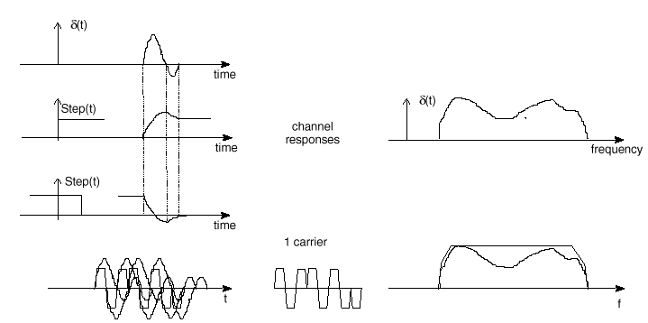
1 carrier transmission

2 carrier parallel transmission

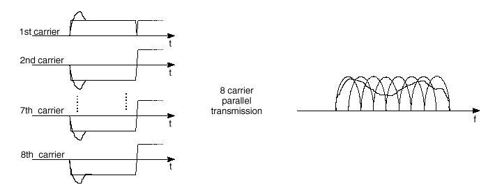
8 carrier parallel transmission
Fig. 3 The effect of adopting a multicarrier system. For a given overall data rate, increasing the number of carriers reduces the data rate that each individual carrier must convey, and hence (for a given modulation system) lengthens the symbol period. This means that the intersymbol interference affects a smaller percentage of each symbol as the number of carriers and hence the symbol period increases (after [10[DM1]]). For example, on the picture is shown a 8 bit long part of a data sequence. For a single carrier system, the responses of individual bits are overlapping, thus creating ISI. Multicarrier system is robust against these physical effects.
In addition, by using a guard interval the sensitivity of the system to delay spread can be reduced [Cimini].
In a classical parallel data system, the total signal frequency band is divided into N non-overlapping frequency subchannels. Each subchannel is modulated with a separate symbol and, then, the N subchannels are frequency multiplexed. There are three schemes that can be used to separate the subbands:
OFDM can be simply defined as a form of multicarrier modulation where its carrier spacing is carefully selected so that each subcarrier is orthogonal to the other subcarriers. As is well known, orthogonal signals can be separated at the receiver by correlation techniques; hence, intersymbol interference among channels can be eliminated. Orthogonality can be achieved by carefully selecting carrier spacing, such as letting the carrier spacing be equal to the reciprocal of the useful symbol period. Mathematical deduction of the orthogonal carrier frequencies is given in [Chang 1966].
In order to occupy sufficient bandwidth to gain advantages of the OFDM system, it would be good to group a number of users together to form a wideband system, in order to interleave data in time and frequency (depends how broad is one user signal).
The importance of coding
The distribution of the data over many carriers means that selective fading will cause some bits to be received in error while others are received correctly. By using an error-correcting code, which adds extra bits at the transmitter, it is possible to correct many or all of the bits that were incorrectly received. The information carried by one of the degraded carriers is corrected, because other information, which is related to it by the error-correcting code, is transmitted in a different part of the multiplex (and, it is hoped, will not suffer from the same deep fade). This accounts for the "coded" part of the name COFDM.
There are many types of error correcting codes, which could be used.
The "orthogonal" part of the OFDM name indicates that there is a precise mathematical relationship between the frequencies of the carriers in the system. In a normal FDM system, the many carriers are spaced apart in such way that the signals can be received using conventional filters and demodulators. In such receivers, guard bands have to be introduced between the different carriers (Fig. 2.), and the introduction of these guard bands in the frequency domain results in a lowering of the spectrum efficiency.
It is possible, however, to arrange the carriers in an OFDM signal so that the sidebands of the individual carriers overlap and the signals can still be received without adjacent carrier interference. In order to do this the carriers must be mathematically orthogonal. The receiver acts as a bank of demodulators, translating each carrier down to DC, the resulting signal then being integrated over a symbol period to recover the raw data. If the other carriers all beat down to frequencies which, in the time domain, have a whole number of cycles in the symbol period (t ), then the integration process results in zero contribution from all these carriers. Thus the carriers are linearly independent (i.e. orthogonal) if the carrier spacing is a multiple of 1/t .
Mathematically, suppose we have a set of signals y , where y p
is the p-th element in the set. The signals are orthogonal if
 ,
,
where the * indicates the complex conjugate and interval [a,b] is a symbol period. A fairly simple mathematical proof exists, that the series sin(mx) for m=1,2,… is orthogonal over the interval -p to p . Much of transform theory makes the use of orthogonal series, although they are by no means the only example.