www.WirelessCommunication.NLChapter: Wireless Channels.
|
| Topographical terrain data is used extensively to predict propagation conditions, before installing cellular base stations. |
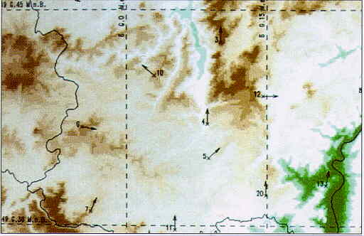 Source: Siemens TORNADO D Cellular Planning Tool |
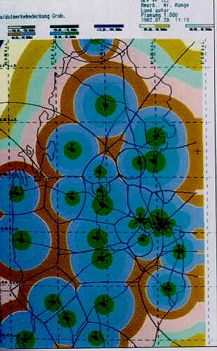
| In a rough coverage estimation, pathloss is computed using a basic propagation model, with considering the topogrphy in great detail. Real-life cell substantially differ from the theoretical hexagonal lay-out. |
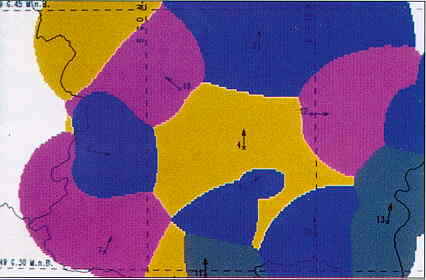 Source: Siemens TORNADO D Cellular Planning Tool |
| Pathloss is computed from the terrain features and antenna data. This determines to coverage of each base station |
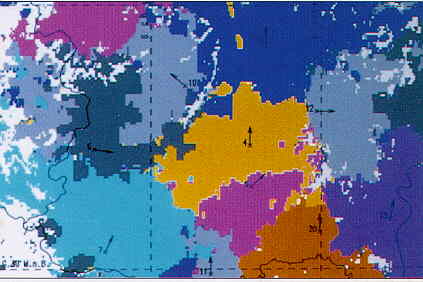 Source: Siemens TORNADO D Cellular Planning Tool |
In the above example, the most appropriate path loss model depends on the location:
| Models such as the Egli Path Loss Law can be used for a rough coverage estimation. Results generated by the TORNADO D planning tool by Siemens AG for cellular telephone at 900 MHz. (Qatar, Arabian Peninsula ) |
 Source: Siemens TORNADO D Cellular Planning Tool |


![]()