|
|
JPL's Wireless Communication Reference WebsiteChapter: Network Concepts and Standards
|
 with contributions by Karin van Dam, Philips Research, Redhill
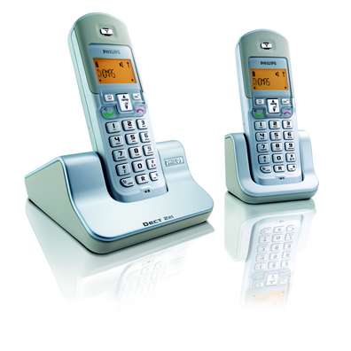
DECT started its life as Digital European Cordless Telephony in the late eighties and has since then had two name changes have reflected a more global deployment and a move to include data as well as voice services.
DECT is well suited to both domestic and business use. Its dynamic channel allocation and digital voice coding provide a voice quality comparable to a landline, while its ability to hand over between base stations make DECT a prime candidate for larger sites, such as offices or industrial buildings.
In addition to home and business use, several extensions to the standard enable DECT to be used as a public access service (CTM - Cordless Terminal Mobility) and a Wireless Local Loop (WLL).
A U.S. version of DECT has also been developed under the acronym PWT, operating in the 2.4GHz ISM band.

In the picture above the yellow squares represent occupied time slots. A connection always uses a pair of time slots separated by one half TDMA frame.
DECT uses Dynamic Channel Allocation (DCA). This means that slots and frequencies are not pre assigned, but each connection automatically selects the channel with the best quality. Since this can change over time, connections may be transferred to another channel which may or may not be with the same base station (handover).
A normal DECT slot is 417 microseconds long and contains 420 bits.

It is made up of the following fields:
The advantages of GFSK can be summarized as follows.
In addition to GFSK, the DECT specification allows three other modulation schemes: p/2 DBPSK, p/4-DQPSK and p/8-D8PSK. While the first of these modulation schemes is compatible with GFSK, the last two provide 2 and 4 times the data rate as GFSK. This means that, combined with the high speed data profile, data rates of up to 2Mbps can be achieved using DECT.
DECT was not designed with a training sequence, thus enabling cheaper terminals that do not have to offer equalisation. However, equalisation can significantly improve DECTs performance over realtively long links (say more than 100 meters) in multipath environments.
 A base station (Fixed Part) always transmits its identity information. If no carrier is in use, a special dummy bearer is set up for this purpose.
In the unlocked state, the Portable Part (handset) scans the DECT slots and frequencies
to find such a transmission from a fixed part. Once it has selected a suitable
fixed part, the portable part will synchronise its timing with that of the
fixed part and keep listening to identity messages from the fixed part. The portable
part is now locked to the fixed part. Note that the fixed part does not know that
the portable part is locked.
A base station (Fixed Part) always transmits its identity information. If no carrier is in use, a special dummy bearer is set up for this purpose.
In the unlocked state, the Portable Part (handset) scans the DECT slots and frequencies
to find such a transmission from a fixed part. Once it has selected a suitable
fixed part, the portable part will synchronise its timing with that of the
fixed part and keep listening to identity messages from the fixed part. The portable
part is now locked to the fixed part. Note that the fixed part does not know that
the portable part is locked.
In DECT the portable part normally initiates setting up a connection. This is done by exchanging a certain set of messages. Once a connection is set up, the fixed part may terminate its dummy bearer as other portable parts can lock to the new traffic bearer. If the fixed part wants to set up a connection, it will page the portable part, which will then initiate the connectio set up procedure.
 DECT offers a number of slot types that vary in length and level of protection.
Voice connections use unprotected slots where the B field consists of 320 data
bits and 4 CRC bits. Speech is coded using a 32kb/s ADPCM CODEC.
DECT offers a number of slot types that vary in length and level of protection.
Voice connections use unprotected slots where the B field consists of 320 data
bits and 4 CRC bits. Speech is coded using a 32kb/s ADPCM CODEC.
In addition to voice, DECT also offers several ways to transmit data using DPRS (DECT Packet Radio Service). This consists of a series of profiles that each allow a particular data service. The DECT data services use the protected B field, which consists of 256 data bits and 68 CRC bits. This increased level of protection that any errors can be resolved using ARQ. Data services can use more than one slot pair per connection, and can use these in symmetric or asymmetric mode. This means that in theory at least, one portable can use 23 slots in one direction, and 1 slot in the reverse direction.
The maximum data rate for GFSK is 552 kbps. With higher level modulation, this can be increased to 2 Mbps.
DPRS supports interworking to all common data standards (V.24, Ethernet)
In order to satisfy the signal strength requirement, a site survey is often carried out. This involves positioning base stations in various locations and measuring the coverage area. Alternatively, software packages are available to perform this task automatically. The picture below was generated using the ray tracing technique. In the picture below, the green crosses represent base station locations and the black lines walls. Walls are specified in terms of composition and materials. The simulation uses ray tracing to determine the path loss in each grid cell. Red cells have a path loss of less than -80 dB and white cells of more than -80 dB.
Pathloss is just one aspect of the coverage of DECT base stations. In practice DECT encounters problems if the delay spread exceeds 90 nanoseconds. At this point, i.e., when the delay spread exceeds about 10% of the symbol duration, intersymbol interference starts to become problematic.
See also:


![]()