 |
JPL's Wireless Communication Reference WebsiteChapter:
Analog and Digital Transmission
|
An antenna array consists of M identical antenna elements, whose operation and timing is usually controlled by one central array processor. The geometry of the antenna locations can vary widely, but the most common configurations are to place the antennas round a circle (circular array) or along a straight line (linear array).
Antenna arrays have frequently been proposed for the operation of RADAR and emitter location finding systems in a military context: it is possible to perform direction finding tasks and to null or cancel out enemy interferers. However, in the context of civilian cellular systems, the aim of the antenna array receiver is purely to provide acceptable error performance and hence maximise the signal-to- interference and noise ratio (SINR) for each user in the system. A diversity antenna array containing M-elements can provide a mean power gain of M over white noise, but suppression of interference from other cellular users is dependent on the form of the received data and the array signal processor which is employed.
 |
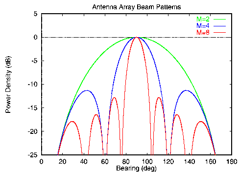
Resulting beam patterns for linear
arrays with different numbers of antenna elements.
As the number of
elements or array aperture increases then the main beam width reduces.
Power Density in (dB) versus Bearing (deg) for Antenna Array Beam Patterns M=2 M=4 Array beam patterns for 0.5 l elementspacing for M = 2, 4 and 8 elements. |
In a power controlled CDMA system the strong desired signal is thus corrupted by a large number of smaller cross-correlation interference terms, which arrive with typically a uniform distribution from throughout the cell. TDMA arrays can usually null out M - 1 interferers, but for a CDMA system this is unlikely to improve significantly the received SINR because of the very large number of interference components.
In general, a better methodology is to estimate the form of the received signal and determine the matched filter solution. This form of receiver can exploit any spatial diversity present, while suppressing the mean level of CDMA interference by a factor proportional to M. Assuming that the antenna array provides significantly improved SINR levels at the base station receiver, the number of channel errors, measured by the bit error ratio (BER), will reduce. This provides the cellular operator with some degrees of freedom which may be used for the following purposes:
The smart antenna problem to improve the reception of the uplink transmissions at the base station is the easiest to manage since here the base station receiver is able to provide an appropriate characterisation of the multipath channel.
In order to fully utilise the improved uplink performance offered by the smart antenna, the downlink performance (from the base station to the mobile or customer premises) must be similarly improved, so that a balanced system is obtained. This is difficult, however, because the gain provided by the smart antenna at the base station be provided (in the form of multi-element antenna array processing) at the mobile or the sub-scriber premises; also, for frequency division duplex the frequency offset between the up and down link transmissions means that the smart antenna solution derived for the uplink may be appropriate for the downlink. An optimum solution to this downlink problem is as yet unknown. Another approach is to recognise this imbalance and simply reallocate more than half of the total available width to the downlink. While smart antenna processing provides many advantages, these must be offset against the cost and of their implementation. There are a number of hardware/software requirements which must be taken into account here: