JPL's Wireless Communication Reference WebsiteChapter: Wireless Channels
|
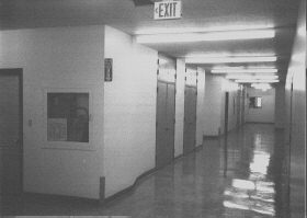
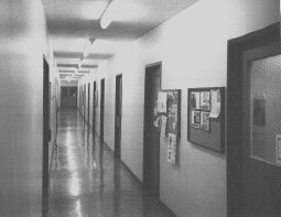
The width of the hallway was less than 8 feet.
     n


p = d,
where d represents distance. In the case of ideal free space
loss, n = 2. We call n the path loss rate.
The drop off rate was significantly smaller than 2.0 which is the value for free space loss. The explanation for this is that the hallway acts as a waveguide given its small width. Note that the received power levels in these Figures are in dB (not in dBm) and are with respect to +10 dBm. To obtain absolute power values in the figure, 10 dB must be added to each component. Note further that n is based on log-log data although the graphs shown are log-linear.
FIGURE: Pathloss in Hallway
Given the proposed InfoPad downlink CDMA chip rate of several tens of Megachips per second, we arrive at 2 Resolvable Paths in this hallway


![]()