GSM Transmit Frequencies
 GSM-like systems have been specified for the 900 MHz (GSM),
1800 MHz (DCS-1800) and 1900 MHz (PCS-1900, USA) radio bands.
In GSM, mobiles transmit in a 890-915 MHz band and receive in
a 935-960 MHz band. The duplex spacing is 45 MHz.
These bands are divided into 125 bands with 200 kHz spacing.
The Absolute Radio Frequency Channel Number (ARFCN)
n (n = 0,1, ... 124) identifies the uplink carrier frequency
890.0 MHz + n 0.2 MHz.
The corresponding downlink is 45 kHz higher.
Extensions (E-GSM) are channel 974 to 1023, which are allocated just
below the original GSM bands.
DCS-1800 uses channel 512 to 885, i.e., carrier frequencies of
1,710.0 MHz + (n-511) 0.2 MHz.
and a duplex spacing of 95 MHz.
PCS-1900 operates in channels numbered from 512 to 810,
with frequencies of
1,850.0 MHz + (n-512) 0.2 MHz.
and a duplex spacing of 80 MHz.
Multiple Access
Each GSM channel uses a TDMA method to
support simultaneous calls from multiple subscribers. Mobile terminals transmit in bursts
of 577 microseconds. One burst fits into one time slot.
Through feedback signals, the system can ensure that
the signals from all users arrive exactly in their assigned time slot,
even if propagation distances to and from different users vary over time.
The terminal has 28 microseconds of guard time to power up
or switch off the RF signal.
It has been noted that this pulsed transmission has may cause some interference the electronic equipment if it is not properly protected.
Particularly airbag ignition circuits
have suffered interference from GSM handset
transmissions.
A set of 8 TDMA slots is called a frame.
In GSM, the terminal transmits and receives
during different times slots. This avoids the expensive
duplex filter that otherwise would have been needed to avoid
that strong transmit signals leak into the receiver.
Burst Structure
A normal burst contains
- 3 tail bits allowing the transmitter to power up.
- 57 coded data bits
- 1 bit stealing flag
- 26 bits training sequence for synchronization
and training of the adaptive equalizer
- 1 bit stealing flag
- 57 coded data bits
- 3 tail bits
- a guard time corresponding to 8.25 bits
Random access bursts carry much less data but have
long guard spacings to avoid that poorly
aligned burst transmissions interfere in other slots.
The frequency correction burst and synchronization bursts allow
proper operation of the terminal.
Frame Structure
The GSM standard distinguishes between physical channels and logical channels. Logical channels carry user speech or data.
Data or signalling messages can travel over different physical channels.
Logical channels can be
- Traffic channels carrying user speech or data
- The full rate channel (TCH/FS) has a net rate of 13 kbit/s.
- The half rate channel (TCH/HS) has been under discussion for a long time.
- TCH/F9.6, 4.8 and 2.4 provides data and fax communication
at 9.6, 4.8 and 2.4 kbit/s respectively. The data occupies a full channel,
but the strength or error protection differs.
- TCH/H4.8 and 2.4 carry data over a half rate channel.
- Control Channels carrying network messages.
Broadcast channels apply only to communication from base station to mobile.
- Broadcast Control Channel (BCCH)
- Frequency Correction Channel (FCCH)
- Synchronization Channel (SCH)
- Common Control Channels (CCCH) support the set-up of
a link between mobile terminal and base station.
- The Random Access Channel (RACH) allows random access by the terminals to initiate a call set-up.
- The base station can initiate a call using the Paging Channel (PCH)
- The base station informs mobiles about which channel to use through the Access Grant Channel (AGCH)
- Dedicated Control Channels (DCCH) carry control messages between network and mobile.
- The Standalone Dedicated Control Channel (SDCCH) is mainly for transfer of signalling between mobile and base station.
- The Slow Associated Control Channel (SDCCH) is mainly used for message to maintain a link.
- The Fast Associated Control Channel (FACCH) is similar to the SDCCH but has more data capacity. This is particularly needed whenever the mobile makes a handover from one cell to another. The FACCH "steals"
transmit resources from the speech traffic channel.
The base station can accommodate these logical channels onto radio carriers
in many different ways.
Traffic Channel Frame Structure
This frame structure uses 26 frames to build a multi frame.
Frames 0 to 11 and 13 to 24 carry speech or user data.
Frame 12 is used as SACCH, Frame 25 is idle, allowing the base station to
measure field strengths from mobiles in other cells, when needed for handovers.
26 frames last 120 msec.
Signaling Frame Structure
The Signaling Frame Structure is a multiframe of 51 frames to accommodate
control channels (FCCH, SCH, BCCH, CCCH) in the downlink and random access (RACH) in the uplink.
The 51-multiframe lasts for 235.38 msec.
Superframes
One superframe contains 1326 TDMA frames (6.12 seconds)
can either carry 51 of 26-Multiframes or 26 of 51-Multiframes.
One hyperframe contains 2048 superframes which
is equivalent to 2,715,648 TDMA frames.
Channel Coding
Speech or user data bits are protected using two concatenated codes.
GSM has blocks of 260 bits, containing 50 class Ia bits, 132 class Ib bits
and 78 Class II bits.
The first step involves block coding.
Three parity bits are added to allow error detection for the first 50 class Ia
bits. 4 bits are added to the Class Ib bits.
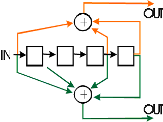
The 189 Class Ia and Ib bits are then convolutionally
encoded at rate 1/2, i.e., the generate 378 code bits.
The coder has constraint length K = 5.
Five consecutive bits are used to create the transmit bits.
Every time one bit is fed into the encoder, two bit appear at the output.
The first output bit is the exor of the input bit with the third and fourth preceding bits.
The second output bit is the exor of the input bit with its immediate
preceding input bit and the third and fourth preceding bits.
|
Figure: Convolutional encoder for transmission in GSM.
Each input bit generates two output bits,
determined by the input bit and four previous bits.
The encoder contains four delay elements (squares
in the Figure).
|

|
The class II bits remain unprotected. Together with 378 coded class I bits,
each block contains 456 bits. These 456 bits are split into 4 bursts of 114 bits each, or 8 subblocks.
If the speech codec receives the information that bits are unreliable it
discards the block of 260 bits and interpolates the speech.
Interleaving
A transmission burst may easily be lost because of channel fading.
Therefore portions of each block of speech data are spread over several
transmission bursts.
Data at 9.6 kbit/s
For reliable communication at a user bit rate of 9.6 kbit/s,
the
data terminal initially encodes the raw data, giving
a bit rate of 12 kbit/s. That is, 12 kbit/s
is the bit rate over the interface between the GSM handset and
the data source (PC, fax or whatever).
The GSM handset then
provides for additional error protection, using convolutional
encoding.
For data transmission the error control and interleaving parameters
differ essentially from the case of speech transmission.
The CRC parity bit are not used for data. The convolutional
encoding still involves rate 1/2 and K=5.
The 244 data bits are encoded into 488 bits.
This exceed the 456 bits that can be accommodated in one block
by 32
bits. So 32 bits redundant bits are left out.
This is called "puncturing".
The interleaving works over 22 frames, to ensure that bursts of errors
are effecitively spread over a longer a period of time.
Modulation
GSM uses Gaussian Minimum Shift Keying (GMSK).


 GSM-like systems have been specified for the 900 MHz (GSM),
1800 MHz (DCS-1800) and 1900 MHz (PCS-1900, USA) radio bands.
In GSM, mobiles transmit in a 890-915 MHz band and receive in
a 935-960 MHz band. The duplex spacing is 45 MHz.
These bands are divided into 125 bands with 200 kHz spacing.
The Absolute Radio Frequency Channel Number (ARFCN)
n (n = 0,1, ... 124) identifies the uplink carrier frequency
