 |
JPL's Wireless Communication Reference WebsiteChapter: Network Concepts and Standards
|
Contributed by Paul G.M. de Bot and Flavio Daffara
Reliable reception of DTTB signals is only possible if good frequency and time synchronization is achieved. To enhance synchronization performance, the DFT blocks, or OFDM symbols, are organized in frames. In the European Digital Video Broadcasting (DVB) project, a frame containing a number of 96 OFDM symbols is proposed, including a silent period (null symbol). This null symbol is used for coarse time synchronization. Immediately after the null symbol, a reference symbol having good autocorrelation properties in the frequency domain is transmitted. This reference symbol is used for coarse frequency synchronization. Since the transmitted content of the reference symbols is known a priori at the receiver side, the receiver is able to estimate the frequency domain transfer function. Hence, the receiver can calculate the time domain transfer function, and is consequently able to determine the optimal observation window position (fine time synchronization). The reference symbol in its turn is followed by a Transmission Parameter Signalling (TPS) symbol, which contains transmission mode information, such as the used signal constellation and convolutional code rate. The TPS symbol is modulated and protected such that it can be received even under very bad channel conditions.

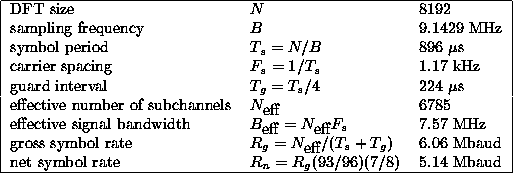
For a DTTB system with the above parameters the symbol rate is 5.14 Mbaud.
Channel amplitude and phase estimation are required for enabling coherent detection of the QAM signals, and for providing reliability information to the soft-decision Viterbi decoders. This channel estimation is performed by using the reference symbol and pilot cells. To obtain information about the frequency domain characteristics of the CCI the null symbol is analyzed. More accurate estimation of the S/(I + N) ratio in each subcarrier can be obtained by examining the statistics of the received signal.