

|
Wireless CommunicationChapter: Analog and Digital
Transmission
|
Based on the discrete frequency channel model, the OFDM receiver sees the signal
Y = Q A + N,
where matrix Q = DIAG(V) + T X DIAG(V’) with X the leakage matrix. Our OFDM receiver is extended such that it can not only reliably estimate amplitudes (as conventional receivers do), but also complex valued derivatives (which is not common for normal OFDM receivers), with V and V’ the estimate of amplitudes and derivatives, respectively. Then the data can be recovered as follows:
W = QH [ Q QH + N0 IN ]-1.
For a receiver that perfectly estimates the channel, the covariance matrix of the residual ICI plus noise, normalized to unity signal power, becomes

The vector of the SINR at the N subcarriers is
diag(Q) .* diag(QH) EN ./ diag(C),
where ./ is a subcarrier-by-subcarrier division and .* a subcarrier-by-subcarrier multiplication. A conventional OFDM link with known channel characteristics (V, V’) would have a noise plus ICI contribution described by covariance matrix:
EN T2X*V’V’HX*H + N0 IN,
The vector of SINR values is found as (15)
diag(Q).*diag(QH) EN./diag(T2X*V’V’HX*H EN+N0IN).
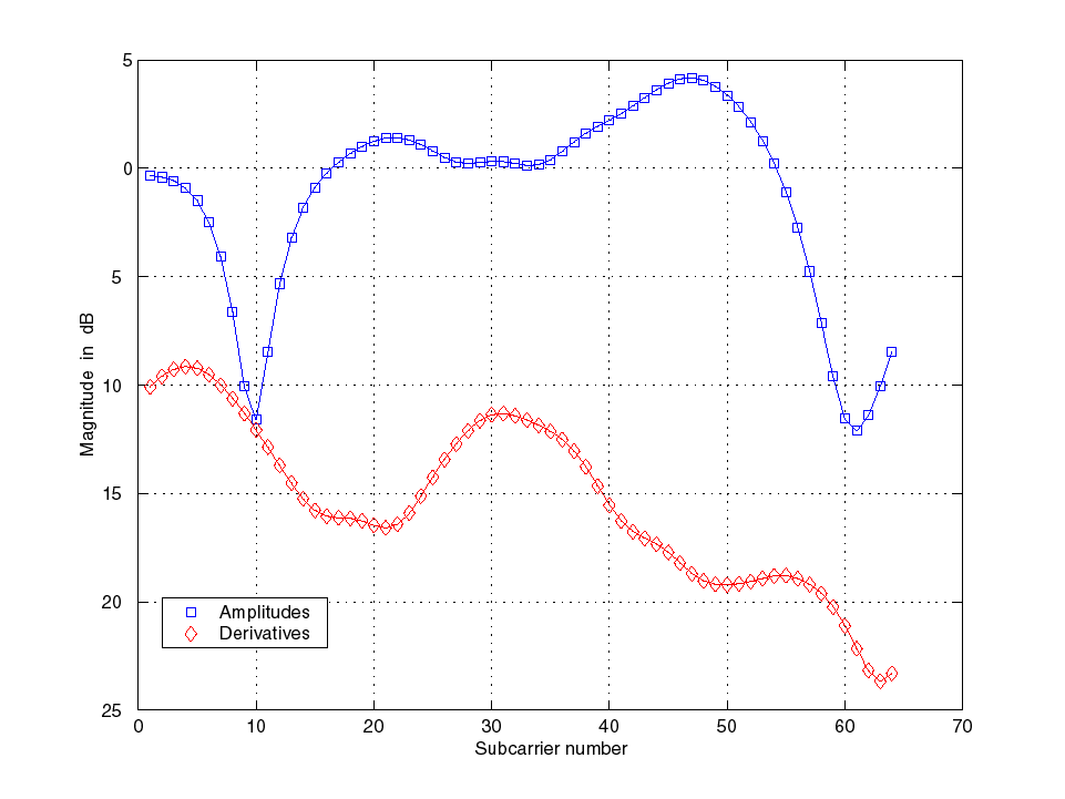
Figure 2: Amplitudes |V+z 0V’T| and derivatives z 0T|V’|, as a function of subcarrier number for a sample channel
We simulated this receiver in Discrete-Frequency domain:
We generate complex fading amplitudes of a Rayleigh channel with Doppler and delay spread from an i.i.d vector of two complex Gaussian random variables G and G’, both with unity variance and length N. The vector G was then multiplied by a precomputed N-by-N matrix U, such that UUH is the channel covariance matrix G with elements G n,m = Evn(0)vm*(0), to create V = U G. Similarly the derivatives are generated from G’ according to V’ = 2p fD T U G’.
We simulated a HIPERLAN II type of system under extreme Doppler conditions. A carrier frequency of fc = 17 GHz, 200 km/h, N = 64 subcarriers, transmit bandwidth of 2 MHz (T = 0.5 m s) and a delay spread of TRMS = 1 m s. EN / N0 = 100 (20 dB). The Doppler spread is fD = 3.148 kHz and fs = 31.25 kHz. So the average SIR for a conventional OFDM system would be around 18 dB. These parameters correspond to the level of ICI experienced in an 8k DVB-T system at normal vehicle speeds. Figure 2 plots an example of the signal amplitude |V+z 0TV’T | and z 0T |V’| as a function of the subcarrier number. Figure 3 gives the SINR after the equalization filter for a conventional OFDM system and our proposed solution.
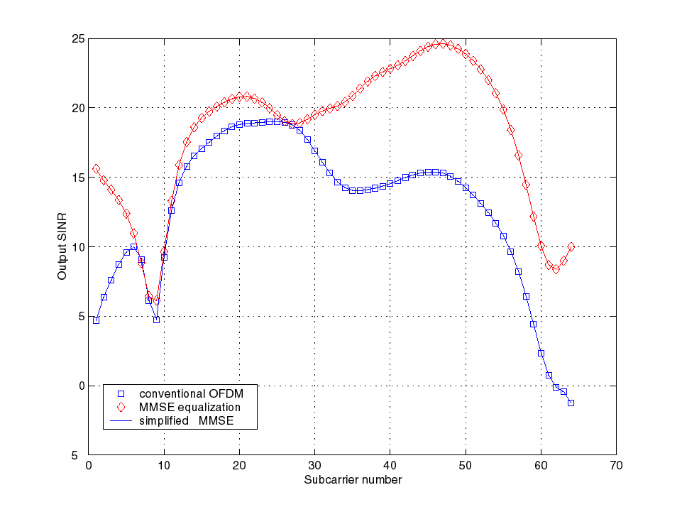
Figures 3: (ð ) Signal-to-ICI-plus-noise ratio in conventional system, (à ) SINR in new system as a function of subcarrier number for the channel in Figure 2.
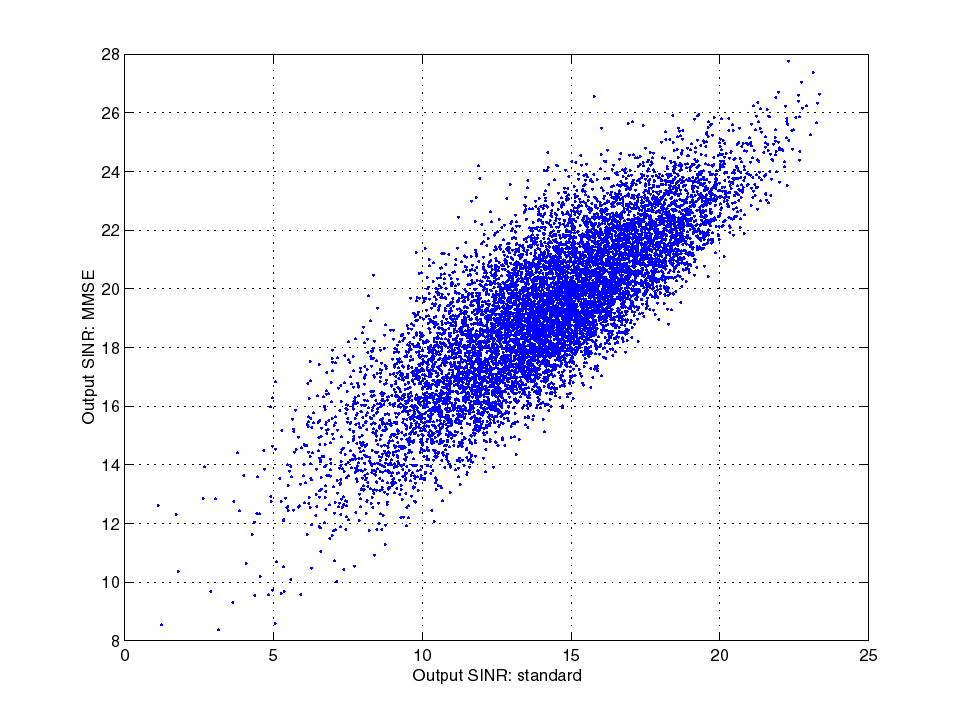
Figures 4: Comparison of SNR in conventional system and SNR in a system with
ICI canceller. Every dot corresponds to one sample channel with N subcarriers.
We used a DFE receiver architecture inspired by the LSE structure. It allows iterative computing to minimize the variance of the error between input and output of the slicer.
The iteration method contains the following steps for iteration round i:
Starting condition is the all-zero vector for V(0), V’(0) and A(0).
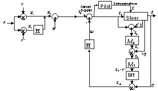
Figure 5: Discrete-frequency domain representation of channel and DFE receiver
The following paragraph addresses the selection of useful choices for the filter in the DFE loop. Filter M6 attempts to recover X3 from Z6 by filtering Z7 = M6 Z6. Using the orthogonality principle, an appropriate (MMSE-like) choice for M6 follows from the requirement
E[(Z7 - X3) Z6H] = 0N
We define e as the vector of decision errors, with e = V.*A - V.*A so for Z6 we write Z6 = X X3 + N + e, and insert this in
M6 E[Z6 Z6H] = E[X3 (X X3 + N + e)H]
Modeling of the terms Ee1e1H, EX3e1H and EX3HX He1 is not straightforward, so next we will search for simplifying approximations. If e were statistically independent of X3, one can significantly simplify these expressions. Although such assumption is questionable, it can lead to a simple and practical receiver design. We simplify the resulting M6 as
M6 = X H [ E[X X H + G ]-1
where G is chosen as G = c1 IN. Exploiting results from a derivation of the OFDM error probability in fading channels, a suitable estimate appears to be
c1 = 2 EN-1(2p fD T)-2 (N0 + EN s error2 / (4(EN / N0 + 1)) )
where s error is the standard deviation for the error in the event that the slicer makes a symbol error, EN / N0 is the average (local-mean) signal to noise ratio (per subcarrier)
As far as M7 is concerned, Z8 approximates V’ however it contains error contributions, due to AWGN and estimation error in A and V. An MMSE filter to estimate Z9 = V’ follows from E (Z9 - V’) Z8H = 0N, thus M7 = EV’Z8H [E Z8 Z8H]-1. We crudely approximate the error terms by assuming that these are independent of V’ and we only consider the main effects, by postulating R3 in
M2 = EV’V’H [EV’V’H + R3]-1
Experiments revealed that R3 a constant times IN is a workable solution.
We simulated the channel in discrete-frequency domain. We took the signal-to-ICI ratio equal to 1200 (31 dB). Local-mean noise is at –40 dB (s n = 0.01c 0). We considered a channel with normalized rms delay spread Trms / Ts = 0.03. This determines the correlation between (derivatives of) amplitudes at different subcarriers. The modulation method is 16 QAM with signal levels at {–3, –1, 1, 3}. In the simulation, we assumed perfect estimates the subcarrier amplitudes. The estimation of derivatives is done iteratively by the DFE loop. The integration constant was set a = 0.9, so V’(i) = 0.9 V’(i-1) + 0.1 Z9(i). The constants have been chosen after a short series of experiments with different values.
In the example run of Figure 6, we see that a conventional system would make errors at subcarrier 3, 4 and 5. The DFE system corrects these errors. In Figure 7, every dot corresponds to one simulation for one particular channel. We see a significant improvement, often of about 10 dB.
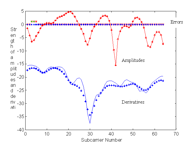
Figure 6: strength in dB of amplitudes 10 log10 diag(VVH) and derivatives 10 log10 diag(V’V’H) (upper and lower solid line) and their estimates (+,· ) after one and many iterations respectively, versus subcarrier number. Also, on same vertical axis, the number of errors per subcarrier: *:errors by conventional system. (· ) errors by proposed system.
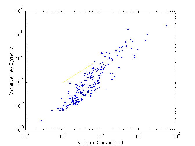
Figure 7: variance of signal before slicer, horizontal: conventional system. vertical: remaining variance after processing in a DFE receiver.
Doppler spread is well recognized as a major problem in mobile OFDM reception. A contermeasure to mitigate this problem can be to considering (i.e., estimating and separating) individual resolvable frequency-shifted components. Estimation, separation and cancellation of these components can become a computationally intensive task, and the effect of signal recovery is sensitive to estimation errors.
Another approach, described here on this page, is to consider the time-varying subcarrier amplitude of each OFDM subcarrier channel as a Taylor expansion with amplitude and derivatives. The receiver uses estimated derivatives. This simplifies the computational burden on the receiver as it limits the number of channel parameters to be estimated. In the receiver evaluated here, we see that the ICI is largely eliminated.
More
The key ideas of this page have been published first in: J.P.M.G. Linnartz and A. Gorokhov, "New Equalization approach for OFDM over dispersive and rapidly time varying channel", PIMRC 2000, London. Related publications: