
|
Wireless CommunicationChapter: Analog and Digital
Transmission
|
This page develops a model for a channel representation starting from the classic multipath description, using a collection of Iw reflected waves. Each wave has its particular Doppler frequency offset w i, path delay Ti and amplitude Di. The frequency offset lies within the Doppler spread -2p fD < w i < 2p fD , with fD = vs fc/c. Here vs is the velocity of the mobile antenna, c is the speed of light and the carrier frequency is w c = 2p fc. More precisely, the Doppler shift of the i-th wave is w i = (2p vs/c) fc cos(q i) with q i the angle of arrival. Let fs denote the spacing between the adjacent subcarriers and w s = 2p fs. The received signal equals

here n(t) is additive white Gaussian noise. We will denote the vector of modulation symbols as A = [a0, a1, ...aN-1]T. The transmit energy per subcarrier is EN = E |an|2. Not all reflected waves are individually ‘resolvable’, that is, a receiver sampling in a time-window of finite duration will only see the collective effect of multiple reflected waves within a certain time-frequency window.
The narrowband mobile channel model can be compacted into a complex received amplitude that is time varying. We rewrite the received signal as
![]()
where the time-varying channel amplitude Vn(t) at the n-th subcarrier is
![]()
A Tayler expansion is Vn(t) = vn(0) (t0)+ vn(1) (t0) (t - t0) + vn(2) (t0) (t -t0)2 / 2 + .. .
See an animation of a Rayleigh fading complex amplitude. Have the amplitude plotted for you live on screen, and imagine what values the derivatives take on.
Here vn(q) (t0) denotes the q-th derivative of the amplitude with respect to time, at instant t = t0. If the Doppler spread is much smaller than the frequency resolution of the FFT grid, we may restrict our analysis to zero and first order effects. In a Rayleigh channel, vn(q) is zero-mean complex Gaussian for any n and q. To characterize the channel, we are interested in the covariance of variables vn(p) and vm(q), viz., Evn(p)vm*(q), where * denotes the complex conjugate. In [20], we have derived this for an exponential delay spread and a uniform angle of arrival. The covariance becomes, for p + q even, (3)

and Evn(p)vm*(q) = 0 for p + q is odd.
In OFDM, a frame of N symbols is detected by taking N samples and performing an FFT. In other words, detection of the signal at subcarrier m occurs by correlation with a complex sinusoid having the frequency of the m-th subcarrier, viz., exp{-jw ct-j(m-D f)w st } during the symbol duration NT. Here Df is the frequency offset normalized to the subcarrier spacing w s. In the sampling process, the receiver makes a timing error t, where D t is the time offset normalized to a sample interval T = (N fs)- 1. That is, it samples at t = Dt, Dt + T, Dt + 2T, ... . We assume that cyclic prefixes avoid any interframe interference. We use Y as the vector of length N to denote the output of the FFT in the receiver. The m-th output of the FFT is found as
![]()
Here, m = 0, 1, ..., N - 1 and Y = [y0 , y1, ... , yN-1]T. We observe that w sT = 2p/N. We introduce the OFDM system parameter xD(q), defined as
![]() ,
,
to describe the signal transfer over the q-th derivative of the amplitude at subcarier n to the (n+D )-th receive subcarrier. This allows us to rewrite ym as follows:

In particular, we will consider the first two terms of the expansion, and we denote cD = xD(0) and zD = xD(1). So,

For integer D , cD reduces to dD , which is just a confirmation that subcarriers (with a nonfading amplitude) are orthogonal. Note further that
![]()
for integer and non-zero D , we see that

Roughly speaking zD / z0 » (jp D )-1, with D = 1, 2, 3, ...., so the ICI reduces slowly with increasing subcarrier separation. Relatively many subcarriers make a significant contribution to the ICI. We define vector V = [v0, v1, .., vN-1] for the subcarrier amplitudes and V’ = [v0(1), v1(1), .., vN-1(1)]T for the derivatives.
For an ideally synchronizing receiver, i.e., with Dt = 0 and Df = 0,, the received signal Y can compactly be written in Discrete Frequency domain as,
![]()
with DIAG(X) the diagonal matrix composed of the elements of vector X, and

Not all terms in X address ICI: In the expression, the diagonal terms z0 carry signal components from the n subcarrier to the n-th subcarrier, so in fact the receiver sees a signal amplitude of (c0 vn + z0 T vn(1))an. To address this in the following calculations we define X* = X - z0 IN. The wanted signal component in a conventional receiver equals V+z0 V’T, which in practice closely approximates V, except in deep fades.
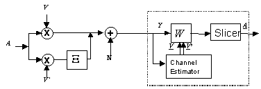
Figure 1 depicts the channel and receiver in the discrete frequency domain. Thus, the FFT is not drawn explicitly. In a conventional system, W represents the equalizer, or automatic gain control per subcarrier, to compensate for fading on the subcarriers.

Figure 1: Discrete-Frequency representation for the Doppler multipath channel and a (feedforward) OFDM receiver
Next: how to build a receiver based on this principle?
The key ideas of this page have been published first in: J.P.M.G. Linnartz and A. Gorokhov, "New Equalization approach for OFDM over dispersive and rapidly time varying channel", PIMRC 2000, London.