 |
JPL's Wireless Communication Reference WebsiteChapter: Analog and Digital Transmission
|
Contributed by Peter M. Grant
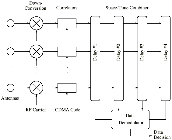
The antenna array receiver aims to estimate the transmitted data sequence d(n), based on the interference corrupted measurements from the K channels. There are two approaches that can be used for combining the data samples. In a single CDMA receiver, K channel taps are combined. This resembles the rake receiver, though not necessarily with the optimized MRC tap weighting. Often non-coherent adding is used for simplicity. A simple approach to designing an antenna array receiver is to employ a rake-like filter to combine all the K * M received data vectors, with M the number of antennas. For DPSK modulation, this is performed with L = K * M. Non-coherent combining of a lot of multichannels can give rise to large losses in SINR compared to maximal ratio combining.
2-D RAKE Filter
A more effective and compact approach to dealing the channel tap vectors is to apply a separate spatial filter to each tap vector in turn. The receiver exploit any structure that might be present, such as the directions of arrival of the multipath components, their Doppler frequencies, etc. This permits the receiver to perform coherent combining of the tap vector elements, improving performance over the 1D RAKE filter.
 |
This means that only K outputs need to be combined using a DPSK demodulation method. The approach has been called the 2D-RAKE filter, because the receiver operates two separate sets of combiners in time and space. The receiver picks out the largest channel taps and selects appropriate spatial filters in each case. The parameter K applies to the number of delays. The outputs from the spatial filter banks are then combined in a conventional RAKE fitter, ready for decision-making. Base-stations are frequently split into three sectors, to provide 120deg. coverage. There are a number of methods to determine the form of the spatial combining filter weights.
Many of these techniques employ the estimation of the covariance matrix ^ Rk of the signal. This task may be performed without the transmitter employing an initial training sequence by using blind channel identification techniques, such as:
This simple technique applies fixed spatial filters or beamformers to achieve a modest improvement in performance.
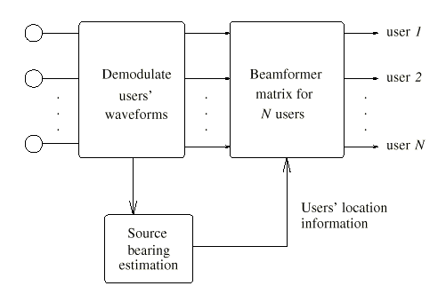
As the received vector is composed of a number of steering vectors, it is possible to apply bearing estimation techniques to the covariance matrix ^ Rk to pick out the major directional components, to determine the direction of arrival (DOA). There are a number of well known high-resolution techniques such as ESPRIT and MUSIC: however, these algorithms have to average over a number of received samples and they perform poorly in the presence of highly correlated multipath signals, which frequently occur in the urban communication channels. A simpler approach is to use the conventional beamformer approaches.
 |
In order to identify the received signal vector it is possible to calculate the eigenvalue decomposition of ^ Rk . Provided the SINR is large, the eigenvector corresponding to the largest eigenvalue of ^ Rk then provides an estimate of the received vector using the statistical method of principal component. This method thus maximizes the SINR to provide a more optimal solution.