 |
JPL's Wireless Communication Reference WebsiteChapter:
Analog and Digital Transmission
|

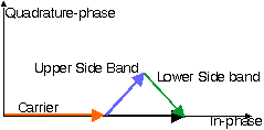
Figure: Phasor Diagram for Narrowband PM with tonal modulation.
In the animation below, we demonstrate the phasor motion for FM with tonal modulation. The three blue phasor represent
Note also that this almost gives exactly a constant envelope for the resulting signal: The phasor black in black has constant length, only its rotation relative to the x-axis changes. This rotation contains the modulated tone signal. In fact we would need to draw more sidebands to ensure an exactly constant envelope. The need for more sidebands implies that the RF bandwidth is larger than twice the bandwidth of the modulating signal.
Java Applet: Phasor diagram of a carrier with FM tone modulation.
Blue: Carrier, and four side components. Black: Composite Signal.
That is, if the FM signal suffers phase distortion due to filtering, the signal will exhibit amplitude modulation effects.