Wireless CommunicationChapter: Network Concepts and
Standards
|
WIND-FLEX ADAPTIVE MODEM ARCHITECTURE
System characteristics overview
A table of most important WIND-FLEX parameters is reported here below:
|
System parameters |
Values |
||
|
Coverage range (omnidirectional antenna, BER 10-6 , code 1/2) |
LOS: £ 100 m (QPSK), £ 50 m (16QAM), £ 30 m (64QAM) NLOS: £ 10 m (QPSK), £ 6 m (16QAM), £ 4 m (64QAM) |
||
|
Radio Interface optimization strategy |
Meet QoS requirements given channel conditions with the minimum transmitted/processing power |
||
|
RF parameters |
Values |
Baseband parameters |
Values |
|
Frequency |
17.1-17.3 GHz |
Modulation scheme |
OFDM with variable number N (1-8) of subcarrier excision |
|
Channel BW |
50 MHz |
Modulation adaptivity |
Per frame, per user |
|
Number of channels |
4 |
Subcarriers modulation schemes |
BPSK, QPSK, 16QAM, 64QAM |
|
Channels center frequencies |
17.125, 17.175, 17.225, 17.275 |
Nominal OFDM carriers number |
128 |
|
Upper guard frequency band |
5,469 MHz (14 Suppressed Carriers) |
Unused carriers |
28 (27+DC) |
|
Lower guard frequency band |
5.078 MHz (13 Suppressed Carriers) |
Active OFDM carriers number |
100 |
|
Subcarrier spacing |
390.625 KHz |
Pilot carriers |
0 |
|
Max peak EIRP |
27 dBm |
Useful OFDM carriers numbers |
100-N |
|
Max average EIRP |
14 dBm |
OFDM useful symbol length |
2.56 m s |
|
Receiver sensitivity |
-85 dBm |
Guard interval |
200 ns |
|
Dynamic range |
60 dB |
Coding scheme |
Turbo code |
|
Noise figure |
6 dB |
Turbo code scheme |
Parallel convolutional punctured |
|
Turbo codes polynomial |
(13, 15) octal |
||
|
Coding rates |
1/2, 2/3, 3/4 |
||
|
Networking parameters |
Values |
||
|
Access scheme |
FDM/TDMA |
||
|
Duplexing scheme |
TDD |
||
|
Symbol slots/frame |
178 |
||
|
Frame length |
491.28 m s |
||
|
Preamble structure |
3 symbols |
||
|
Network entities |
Master, slaves, bridge, gateway |
||
|
Network entity allocation |
Dynamic |
||
Baseband architecture
WIND-FLEX baseband architecture is based on Turbo channel coding, OFDM modulation scheme and a "Supervisor" (SPV) unit for real-time system optimization (see Figure 4).
The available subcarrier modulation schemes are BPSK, QPSK, 16-QAM and 64-QAM. The constellation is adaptively chosen among the various schemes and a variable number of subcarriers can be also adaptively switched-off. Moreover, to save processing power, a scalable (I)FFT structure is adopted.
The coding scheme of the WIND-FLEX modem is a parallel convolutional turbo code. The available code rates are 1/2, 2/3 and 3/4 and the block length is adaptive and dependent on the triplet: Code rate, Constellation size, and Number of ON subcarriers.
The WIND-FLEX SPV task is to solve the problem of fitting the QoS requirements from the MAC layer, given the current channel conditions, with the minimum transmitted/processing power. To get this result, the SPV finds the best configuration of the transmission system and sets the best values for the transmission parameters.
The optimization procedure relies on the channel reciprocity hypothesis, satisfied because of the TDMA/TDD nature of the frame and of the adoption of single antenna transceivers. Channel reciprocity allows open loop adaptivity.
RF/IF front-end architecture
OFDM is a quite demanding technique in terms of phase noise and frequency stability particularly for higher order constellations (i.e. 64-QAM). The RF/IF architectures (Figure 5, 6) can be designed in order to keep a low cost design while achieving low phase noise and high frequency stability according to specifications. As far as the filters are concerned, given the fact that broad channel bandwidth (i.e. 50 MHz) doesn't require the use of expensive components such as SAW or ceramic filters, low cost filters based on microstrip or discrete devices can be adopted for the design.
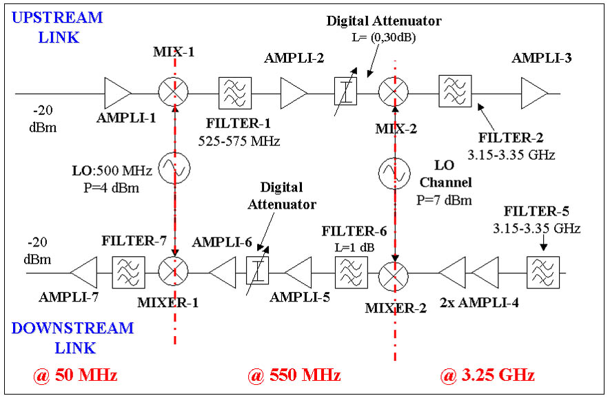 The use of a free
running dielectric oscillator (13.950 LO in Figure 5) allows for low phase noise
and low costs. The required frequency stability in the working temperatures
range can be achieved by a coarse tuning obtained by an IF oscillator controlled
by the baseband. Fine frequency tuning can be obtained within the baseband.
The use of a free
running dielectric oscillator (13.950 LO in Figure 5) allows for low phase noise
and low costs. The required frequency stability in the working temperatures
range can be achieved by a coarse tuning obtained by an IF oscillator controlled
by the baseband. Fine frequency tuning can be obtained within the baseband.
The RF unit can be manufactured at very low costs by relying on advanced SiGe technology processes (i.e. QuBic5G). Because of the high peak to average power ratio nature of OFDM signals (about 13 dB) particular care must be given to the characteristics of power amplifier.
Antenna
In order to guarantee the presence of a reciprocal channel, allowing WIND-FLEX transmitter to perform adaptive controls (see Baseband section) on the basis of channel information estimated by the co-located receiver, the design required the presence of a single antenna, switched between transmitting and receiving phases. Given the mobile and ad-hoc network nature of WIND-FLEX an omni-directional antenna is compulsory.
For this particular design, printed technology antennas provide a number of advantages as lightweight, low costs and relatively easy manufacturing. Among the different possibilities the line fed slot coupled microstrip patches is considered suitable as this technique makes relatively easier the impedance matching and facilitates fed network design for array configurations. Restrictive specifications for bandwidth in terms of return losses have to be given in order to provide the required bandwidths.
Technology for high volume production
For the high volume production the use of a multi-layer PCB structure with some filters and the MMICs mounted in the top layer and other filters in the intermediate layers is envisaged. This structure would minimise the size of the PCB and avoid the radiation of the filters. Four MMICs are envisaged for the chip-set with the size and technology indicated in table 2.
|
Unit |
Ranges |
Estimated size |
Technology |
|
IF Transmitter |
50 MHz-3,25 GHz |
6 mm x 5 mm |
Si-Ge |
|
IF Receiver |
3,25 GHz-50 MHz |
6 mm x 5 mm |
Si-Ge |
|
Transmitter RF |
3,25GHz-17 GHz |
2 mm x 2 mm |
GaAs/ Si-Ge |
|
Receiver RF |
17GHz-3,25 GHz |
2 mm x 2 mm |
GaAs/ Si-Ge |
Table 2: Chip-set for high volume production of WIND-FLEX modem
A dielectric substrate of low losses should be used for the PCB. In order of reducing the size of the PCB, a substrate of high dielectric constant such as a ceramic of dielectric constant around 6 should be used. With this kind of substrate the size of the PCB for both units RF and IF would be of around 5cm x 5cm. Four layers are envisaged for the PCB with this substrate. The packages must be compatible with a high volume manufacturing process such as SMD. There are no problems for the IF chips for which plastic packages could be used but, however, these kind of packages are not available up to now for 17 GHz. Wire bonding must be avoided because it requires very sophisticated facilities for volume production. Flip-chip technology may be the most adequate. The entire radiofrequency unit must be enclosed by a metallic enclosure manufactured by an injection moulding process.
Network Architecture
The WIND-FLEX Network is composed by a set of clusters, being this set of devices such that every pair can establish a direct connection; a cluster is then a full-meshed sub-network. Every cluster consists of a Master device and of one or more (up to 63) Slave devices, which must perform an appropriate association procedure to the cluster. The Master carries out the synchronization and the coordination of the cluster and it is in charge of allocating the shared radio resources. There is no hardware or software difference among the Master and Slave devices, and each device can become a Master. The Master of a cluster is chosen among all the devices associated to the cluster: a Master election procedure ensures that the Master is the device having the "best" position within the cluster, meaning that its physical links with all the other devices associated to the cluster are characterized by the best quality. A proper algorithm guarantees that the Master election is repeated whenever, mainly due to device movement, the network topology significantly changes. In case a new Master is elected, the Master role is handed-over in a seamless fashion from the old Master to the new one [9, 10]. The system is able to reconfigure itself to react to changes in the network topology. The WIND-FLEX protocol stack is fully based on IP as depicted in Figure 7.
Medium Access Control (MAC) Layer
At MAC layer the bit transmission is organized in a Time Division Multiple Access (TDMA) way. The time axis is divided into frames that, in turn, are divided into 178 time slots, characterized by:
In order to reduce battery consumption, data transmission speed is reduced whenever the traffic situation allows the delivery of the packets with an acceptable end-to-end delay and jitter delay using a lower transmission bit rate. On the contrary, when traffic is heavy and buffer length is large, the system attempt to use a bigger constellation scheme (up to 64-QAM), provided that channel status is so good that the required BER can be accomplished.
Resource assignment is performed by the Master using a novel greedy-type scheduler algorithm, where the useful slots are assigned frame-by-frame to the different connections of all the devices in the cluster. Such assignment is based on the following two types of information for each active connection:
Data Link Control (DLC) layer
A specific requirement for the WIND-FLEX DLC is quick and dynamic adaptivity to changes in the physical link. The upper interface of DLC protocol serves the network layer, which in the case of WIND-FLEX, is the Internet Protocol, IPv4 or IPv6. DLC provides functions to transmit IP datagrams over the WIND-FLEX air interface to a peer Internet Protocol entity, mapping the IP datagram into different Class of Service, characterized by different QoS requirements.
The data exchange between two DLC entities is always connection-oriented.
At DLC layer runs also a suitable error control protocol, which works on a per-connection basis considering different QoS requirements of the different classes of service. The error control scheme adopted is Selective Repeat ARQ with partial bitmap, which offers good performance but also optimizes retransmission overhead. Acknowledgements are sent selectively to request the retransmission of corrupted or lost PDUs, either in a piggybacked fashion or by means of a control PDU. Sequence Numbers are used to guarantee flow control.


![]()